866-893-2090 sales@c6performance.com
- Home
-
Products
- C8 Corvette LT2 LT6 LT7 E-Ray
- C8 Corvette Air Intakes
- C8 Corvette Apparel/Accessories
- C8 Corvette Brakes
- C8 Corvette Car Care
- C8 Corvette CONCEPT8
- C8 Corvette Custom Painted
- C8 Corvette Electronics
- C8 Corvette Driveline
- C8 Corvette Exhaust
- C8 Corvette Engine
- C8 Corvette Exterior
- C8 Engine Dress Up
- C8 Corvette Floor Mats
- C8 Corvette Graphics, Emblems
- C8 Corvette Interior
- C8 Corvette Nitrous Systems
- C8 Corvette Performance Packages
- C8 Corvette Suspension
- C8 Corvette Superchargers
- C8 Corvette Service Tools
- C8 Corvette Tuners, Programming
- C8 Corvette Turbos
- C8 Corvette Lighting
- C8 Corvette Racing Gear
- C8 Corvette Wheels
- C8 Corvette Z06 WideBody
- C7 Stingray, Z06, GS, ZR1
- C7 Corvette Air Intakes
- C7 Corvette Accessories
- C7 Stingray / Z06 / GS Gifts
- C7 Corvette Apparel
- C7 Corvette Audio, Radar
- C7 Corvette Brakes
- C7 Corvette Car Care
- C7 Corvette Car Covers
- C7 Corvette Carbon Fiber
- C7 Corvette CHROME
- C7 Corvette Concept7
- C7 Corvette Driveline, Drivetain
- C7 Corvette Emblems, Decals
- C7 Corvette Racing Stripe Decals
- C7 Corvette Engine Dress Up
- C7 Corvette Engine LT1/LT4/LT5
- C7 Corvette Exhaust
- C7 Corvette Exterior
- C7 Stingray / Z06 / GS Interior
- C7 Corvette Floor Mats
- C7 Corvette Lighting
- C7 Corvette Nitrous Oxide
- C7 Performance Packages
- C7 Corvette Programmers
- C7 Corvette Racing Gear
- C7 Corvette Superchargers
- C7 Corvette Suspension
- C7 Corvette Tires
- C7 Stingray, Z06, ZR1 Wheels
- C7 Corvette Tuning
- C7 Corvette Widebody
- C7 Grand Sport
- C7 Z06 Corvette LT4
- C7 ZR1 Corvette LT5
- C5 C6 Z06 ZR1 GS Corvette
- 2010-13 Grand Sport Corvette
- Air Intakes - Corvette
- Apparel and Accessories
- Corvette Audio/Electronics
- Corvette Brakes
- Corvette Car Care
- Corvette Car Covers
- Corvette Drivetrain
- Corvette Engine Performance
- A/C Compressors
- Blocks & Strokers
- C5 / Z06 Engine Dress-up
- C6/C5 Corvette CHROME
- C6/GS/Z06/ZR1 Engine Dress-up
- Camshafts & Valvetrain
- Corvette Cooling
- Corvette Lubrication
- Corvette Plumbing
- Corvette Synthetic Fluids
- Cylinder Heads
- Fastners, Bolts, Studs
- Gauges, Shift Lights, Mounts
- Ignition/Fuel
- Intake Manifolds, Throttle Bodies
- LS Engine Components
- Misc. Engine Parts
- Crate Engines
- Corvette Floor Mats
- Corvette Ladies Apparel
- Corvette Race Gear
- Corvette Seat Covers, Protection
- Corvette Tools
- Decals, Graphics, Emblems, Stripes
- Exhaust - C5/C6 Corvette
- Exterior - Corvette
- Group Purchase
- Interior - Corvette
- Lighting - Corvette
- Nitrous Systems Corvette
- Performance Packages
- Performance Tuning
- Pitstop Furniture
- Superchargers/Turbo
- Suspension - Corvette
- Wheels / Tires Corvette
- ZR1 Carbon Fiber 2009-13
- 2010-2015 Camaro, 5th Gen
- Camaro 2010 Apparel/Accessories
- Camaro 2010 Audio
- Camaro 2010 Body Kits
- Camaro 2010 Brakes
- Camaro 2010 Car Care
- Camaro 2010 Drivetrain
- Camaro 2010 Engine
- Camaro 2010 Exhaust
- Camaro 2010 Exterior
- Camaro 2010 Graphics
- Camaro 2010 Interior
- Camaro 2010 Lighting
- Camaro 2010 Nitrous Oxide Systems
- Camaro 2010 Performance Parts
- Camaro 2010 Supercharger
- Camaro 2010 Suspension
- Camaro 2010 Tuning
- Camaro 2010 Turbo Systems
- Camaro 2010 Wheels/Tires
- Camaro Accessories
- Camaro Car Covers
- Camaro Decals, Emblems, Stripes
- Camaro Floor Mats
- Camaro Racing Gear
- Custom Painted Camaro Parts
- Vehicle Fluids
- 2016-2024 Camaro, 6th Gen
- 6th Gen Accessories/Apparel
- 6th Gen Air intakes
- 6th Gen Camaro Brakes
- 6th Gen Camaro Car Audio
- 6th Gen Camaro Car Covers
- 6th Gen Camaro Carbon Fiber
- 6th Gen Camaro Cooling
- 6th Gen Camaro Custom Painted
- 6th Gen Camaro Decals, Emblems
- 6th Gen Camaro Drivetrain
- 6th Gen Camaro Engine
- 6th Gen Camaro Engine Dress up
- 6th Gen Camaro Exhaust
- 6th Gen Camaro Exterior
- 6th Gen Camaro Interior
- 6th Gen Camaro Lighting
- 6th Gen Camaro Nitrous Systems
- 6th Gen Camaro Racing Gear
- 6th Gen Camaro Racing Stripes
- 6th Gen Camaro Superchargers
- 6th Gen Camaro Suspension
- 6th Gen Camaro Tuning
- 6th Gen Camaro Wheels
- 6th Gen Car Care
- 6th Gen Graphics, Stripes
- Camaro 6th Floor Mats
- 1982-2002 Camaro/Trans AM
- C4, C4/ZR1 Corvette 84-96
- C3 Corvette 68-82
- C2 Corvette 63-67
- C1 Corvette 53-62
- Corvette Collection Apparel
- All Vehicles
- Cadillac CTS, 2000-2024
- Ford Mustang
- New Products
- SPECIALS
- C8 Corvette LT2 LT6 LT7 E-Ray
- Featured
- Specials
- New Products
- My Account
- BLOG
- Newsletter
Categories
Information
Manufacturers
Featured
Latest products
| Product 48 of 270 in category Camshafts & Valvetrain | |
Categories
Information
Manufacturers
Featured
Latest products
- Shopping Cart 0 items
My Account Info
Live Support
Advanced Search
Latest Specials
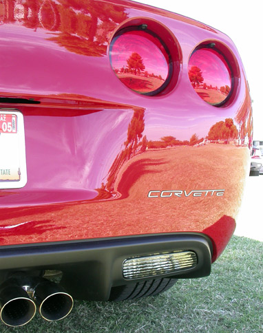
C6 "CORVETTE" Mirror Finish Rear Stainless Steel Letter Inserts, Fits all Model C6 Corvette
Notifications
Payments Accepted
Trade Associations
|

